Instruction Cycle Example
Let’s suppose we have two numbers we want the computer to add for us, and we want to store the result for later use. We will create a program to do this and these two numbers will be its data, stored in Main Memory with the rest of the program.
The ALU is the part of the CPU that can add numbers, but it can only deal with data stored in the data registers, and put its results back into a data register, so our program will need to copy its data from MM to the registers, and copy the result back again.
So our program might look something like:
|
Assembly Language
Instruction |
Meaning |
|
LOAD MM110 R0 |
copy the data from Main Memory address 110 to Data Register 0 |
|
LOAD MM111 R1 |
copy the data from Main Memory address 111 to Data Register 1 |
|
ADD R0 R1 R2 |
have the ALU add the data in Data Register 0 to the data in Data
Register 1 and put the result in Data Register 2 |
|
STORE R2 MM112 |
copy the data from Data Register 2 to Main Memory address 112 |
This program adds the number in memory location 110 to the number in memory location 111 and puts the result in memory location 112.
This example is written in assembly language rather than using machine language, so that we can read it. Similarly, data in examples will be written in decimal instead of binary. MM in front of a number indicates that it is an address in Main Memory. R in front of a number indicates that it is the number of a data register in the CPU.
The program first gets the two numbers from where they are stored in Main Memory and copies them into data registers in the CPU. The Assembly for copying data from MM to data registers uses “LOAD” then the source, then the destination.
Then it adds the contents of those registers, putting the result in a third register. The assembly language for adding uses “ADD” then the two numbers to be added, and then the location for the result.
Finally, it copies the result from that register back to Main Memory at location 112. The assembly language for copying from data registers to MM uses “STORE” then the source, then the destination[1].
For this program to run, we will have to put it at some location in MM, including putting the program’s data in the MM addresses used in the program. For the program to run, we also need the program counter set to the address in memory of the first instruction.
In this example, I picked MM98 as the location for the first instruction. For the program to run, the PC has to start off holding that address.

Fetch
We want to run the first instruction, but to do this we need to get the instruction into the IR, so we can decode and then execute it.
There could be millions of instructions in MM, so to know which instruction to get next, the CPU looks at the PC. The number in the PC tells us which line in memory to copy the instruction from.
So, the CPU copies the instruction from the memory address given by the PC into the IR.
Note: during Fetch we are always copying instructions into the IR. During execute we will sometimes also copy data into Data Registers. We never copy data during Fetch. We never copy to the IR during Execute

So, in this case, what happens during Fetch could be described as:
Copy instruction (LOAD MM 110 R0) from address given in PC (MM98) into IR
Fetch always does the same thing. It always copies some instruction into the IR, and the address to copy from is always found in the PC. So we could always say something like:
“PC says MM(fill in the address) so copy instruction (fill in the instruction) into the IR.”
Decode
We need to set up the electronics so we can execute the
current instruction, the one we just fetched into the IR. This means activating some parts of the
hardware and not others.
For the purposes of this course, we are leaving out a lot of detail in this step; in real computers, the CPU contains a component called the Control Unit, which deals with decoding.
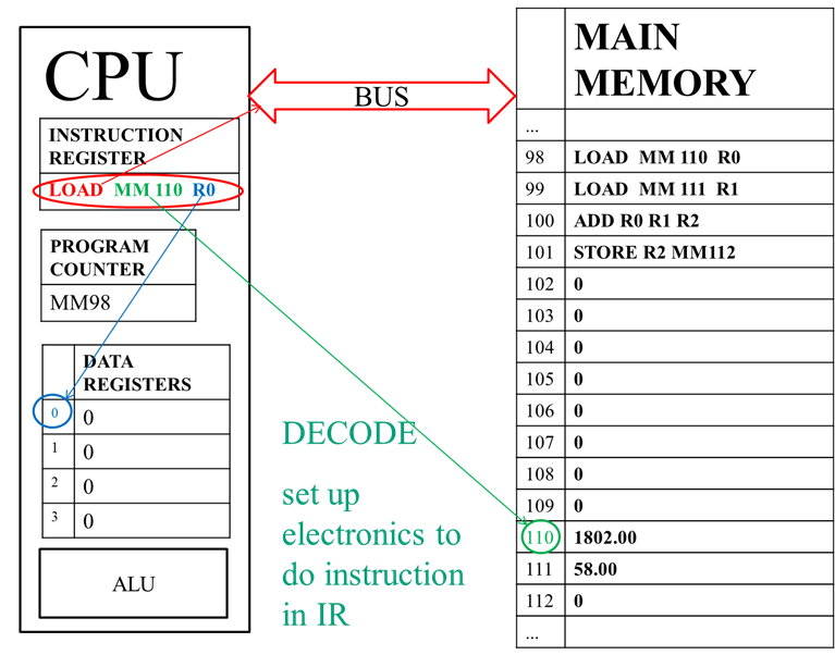
Since we aren’t going into that level of detail, we might simply always say “Set up the electronics to do the instruction in the IR.”
In this case, specifically, we will set up to copy data from MM 110 into R0. This means we must activate the bus, but not the ALU, request MM 110 from MM, and set up the bus so that whatever comes back across is put into R0.
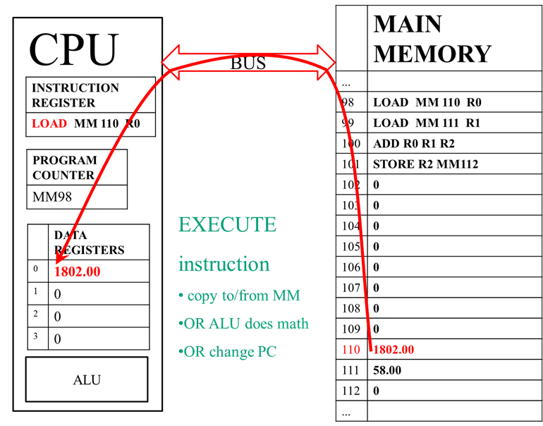
Execute
Now we can finally do the instruction. This step depends on what instruction we’re doing. It could be
· copying data between MM and data registers
· the ALU doing math on numbers in the data registers
· changing the PC, to change what instruction we do next
· other more complex tasks outside the scope of this class
We need to do what the instruction says, but for most instructions,
how that happens will depend on the actual values of data stored when the
instruction runs.
So you don’t have to remember assembly language, a list of
definitions for the instructions in this example was given. LOAD MM 110 R0 means “copy the data from Main Memory address 110 to Data Register 0” So all we need to add is, what was the
specific data involved in this instruction when the program ran?
Since the data in MM110 is currently 1802.00, what happens during execute in this case is, “Copy the data (1802.00) from Main Memory address 110 to Data Register 0” .
Update
We are now done with this one instruction, but the CPU
continues its cycle, so we need to set up for the next Fetch so the program can
continue.
We need to change the PC so that it holds the right memory address for the next instruction, which is the next MM address. So we need to add 1 to the memory address in the PC.

So, in this case we need to update the PC from MM98 to MM99. Like Fetch, this is a stage in the cycle that always takes the same form; we are always updating the PC, and always from the current value to that value plus 1. So in general we could say:
“PC MM(fill in the address) à MM(previous address plus 1)”
Doing an Instruction Cycle Problem
PC = MM99
When doing an instruction cycle problem, remember that everything depends on the PC, which tells us which instruction to fetch. Even if that doesn’t happen to be the earliest instruction visible in MM, the CPU always depends on the PC to know what to do.
At the end of the previous instruction, the PC was updated to MM99.
So what do we already know about the next cycle? It will have to be something like:
1. Fetch: PC says MM(fill in the address) so copy instruction (fill in the instruction) into the IR.
2. Decode: Set up the electronics to do the instruction in the IR.
3. Execute: (depends what the instruction says to do)
4. Update: PC MM(fill in the address) à MM(previous address plus 1)

So, looking at the situation, for Fetch, we see the MM address in the PC is MM99, and the instruction at that address is “LOAD MM 111 R1” So now we can say:
Fetch: PC says MM99 so copy instruction “LOAD MM 111 R1” into the IR.
For Decode, since we’re leaving out the more complex details, we can just say:
Decode: Set up the electronics to do the instruction in the IR.
For Execute, we need to do whatever the instruction says to do, factoring in the current data value(s) involved. Looking back again at the definitions of the instructions, LOAD MM 111 R1 means “copy the data from Main Memory address 111 to Data Register 1” and the value in MM111 is currently 58.00 so we’d say:
Execute: copy the
data from Main Memory address 111 (58.00) to Data Register 1.
Finally, for update,
we need to look at the current value in the PC, and then add 1. The PC has MM99, so we’d say
Update: PC MM99 à MM100
MM100
Following the same pattern, for the next instruction, the PC
holds MM100, the instruction at that address is “ADD R0 R1 R2” and the definition of that instruction is “have the ALU add
the data in Data Register 0 to the data in Data Register 1 and put the result
in Data Register 2”. In this case there
is more than one data value involved: there are two values being added, 1802.00
from R0 and 58 from R1; but also remember that the result is also always data,
so the sum 1860.00 is part of the execution as well.
Let’s fill this in:
1. Fetch: PC says MM100 so copy instruction “ADD R0 R1 R2” into the IR.
2. Decode: Set up the electronics to do the instruction in the IR.
3. Execute: Have the ALU add the data in Data Register 0 (1802.00) to the data in Data Register 1 (58.00) and put the result (1860.00) in Data Register 2
4. Update: PC MM100 à MM101
MM101
Following the pattern again, now the PC holds MM101, the
instruction at that address is “STORE
R2 MM112” the definition of that instruction is “copy the data from Data
Register 2 to Main Memory address 112” and the data in R2 is 1860.00.
We happen to know
that this is the last instruction in the program, so it might be tempting to
say that we shouldn’t do an Update for this cycle, or that we should look for a
later instruction in MM to jump to.
Remember that the CPU can’t see what’s in MM until it is fetched, and
won’t know that a pattern isn’t a valid instruction until it is decoded, and
even if it could see that, the CPU doesn’t know about programs, only the
Instruction Cycle. So the CPU will
follow the cycle as always (if the next pattern fetched really isn’t a valid
instruction, the CPU will react by jumping to the first instruction in a
program that handles such errors).
Let’s fill this in:
1. Fetch: PC says MM101 so copy instruction “STORE R2 MM112” into the IR.
2. Decode: Set up the electronics to do the instruction in the IR.
3. Execute: copy the data from Data Register 2 (1860.00) to Main Memory address 112
4. Update: PC MM101 à MM102
When doing problems like this, you can choose to always follow this pattern. However you can also describe things in other words, as long as you include this minimum amount of information.
1. Fetch: Since the PC says MM101 we need to get the current instruction (“STORE R2 MM112”) from that MM address into the IR.
2. Decode: Set up to do “STORE R2 MM112” by activating the bus, requesting that the data coming from the bus is put in address 112 in main memory, and connecting the input to the bus to data register #2.
3. Execute: 1860.00 is copied from Data Register 2 to Main Memory address 112
4. Update: To prepare for the next instruction the program counter’s value is updated from MM101 to MM102